Concrete Repair and Structural Rehabilitation: Diagnosis First
Written for structural consultants, PMC engineers and facility owners in Delhi NCR and across India who have a distressed concrete element in front of them and need to decide what is actually wrong, what system fixes it, and how to police the work on site.
What this guide settles
Concrete repair is a diagnostic discipline before it is a materials one. Identify the mechanism first: carbonation, chloride ingress, structural overload, construction defect or water movement. Break out to sound concrete behind the reinforcement, clean the steel to bright metal, control the corrosion cell with embedded galvanic anodes, then reinstate with a repair mortar matched to the parent concrete’s stiffness. Finish by removing the water or chloride source. A patch applied without this sequence commonly fails within one to three years through incipient-anode corrosion at its own edges.
What does the distress actually look like on your structure?
Pick the condition that matches your project. The specification, the build-up and the products update as you choose.
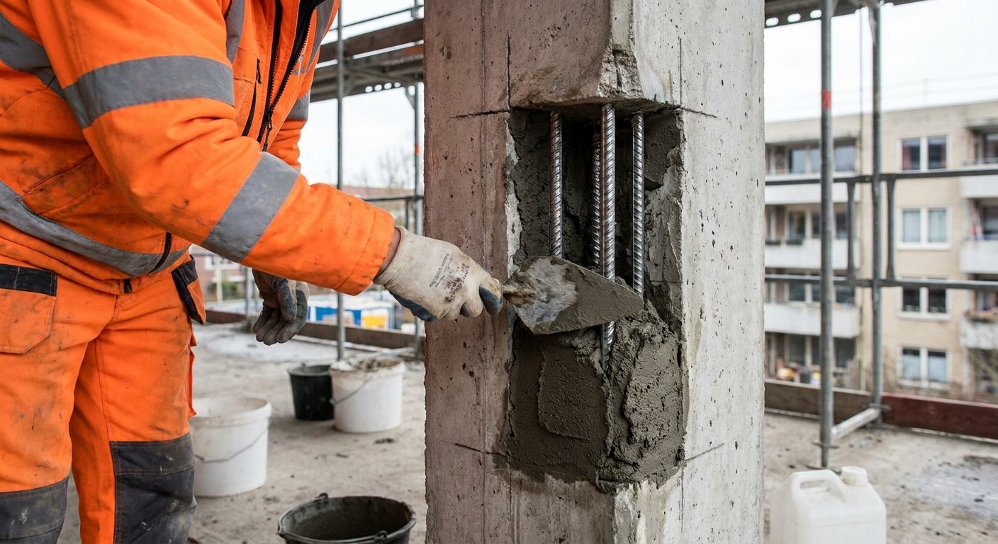
Break back behind the bar, clean the steel, install perimeter anodes, then reinstate with a Class R4 polymer-modified mortar.
The rust you can see is the end of the process, not the start. Chloride or carbonation has depassivated the steel and the expanding oxide split the cover. Reinstating the patch alone leaves the surrounding contaminated concrete cathodic to the new alkaline repair, which drives fresh corrosion at the patch edge within one to three years.
- Saw-cut patch perimeter 10 mm deep; break back to sound concrete, no feather edges
- Break 20-25 mm clear behind the bar; clean steel to bright metal, Sa 2.5 minimum
- Tie galvanic anodes to cleaned bar at 300-600 mm centres; confirm electrical continuity
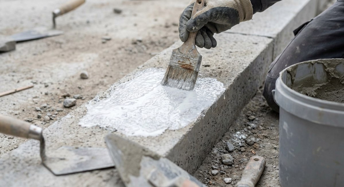
- Apply epoxy or acrylic bond coat and place Class R4 mortar (45 MPa and 2.0 MPa bond minimum) wet-on-wet in 5-50 mm lifts
- Wet cure 3-7 days, then anti-carbonation or chloride-barrier coating over the whole face
Do not inject. Diagnose whether it is plastic shrinkage, drying shrinkage or alkali-silica reaction before spending anything.
Map cracking is a surface-driven pattern, usually plastic shrinkage from a badly cured pour or drying shrinkage in a rich screed. Injection wastes money because the cracks are shallow and dormant. If cores show reactive gel and the pattern is on an old, persistently wet element, the mechanism is alkali-silica reaction and no coating will stop it.
- Map crack widths and depth; take cores if ASR or delayed ettringite is suspected
- Confirm cracks are dormant with crack gauges over one full thermal cycle
- Wash and dry the surface; do not apply anything over a damp, salt-bearing face
- Seal with a flexible anti-carbonation or elastomeric coating from the protective-coatings range, not a rigid epoxy skim or fairing coat
- Where a floor must carry wheels, gravity-feed a self-levelling epoxy into the cracks
Establish whether the crack is live before choosing anything. Dormant means epoxy injection; live means stitching or strengthening, then a flexible seal.
A single wide crack on a load path is a structural signal, not a durability defect. Injecting a moving crack with rigid epoxy just relocates it a few millimetres away. Confirm the cause first with load history, crack gauges and a check of the original design; strengthening may be required whether or not the crack is injected.
- Monitor with crack gauges through one hot and one cool cycle before deciding
- Prop the member if the crack is wide, growing, or on a shear line
- Seal the crack face, fix ports at 150-300 mm centres, inject epoxy low to high
- Where the crack is live, first remove or accommodate the cause: a movement joint, a restraint release, or strengthening that reduces the strain; only then stitch across it with CFRP plates set in grooves, and seal the crack itself with a flexible sealant, never rigid resin
- Strengthen with bonded CFRP fabric or plate if the section is genuinely deficient
Cut out to fully sound concrete and reinstate with formed micro-concrete or high-build mortar, never a skim over the surface.
Honeycombing is almost always deeper than it looks and often runs to the far face. A cosmetic render over it traps a permanent moisture and chloride path straight to the reinforcement. The real decision is whether the void is deep enough to need formwork and a pourable mix rather than a trowelled mortar.
- Sound the area and cut out until the hammer rings solid on every edge
- Check for a through-void; light the far face before assuming it is one-sided
- Clean and treat any exposed bars, then bring the substrate to saturated surface dry
- Under 50 mm: high-build repair mortar in keyed lifts with a bond coat
- Over 50 mm or congested: form a bay and pour shrinkage-compensated micro-concrete
- Strike after 24 hours, cure 7 days, then sound the whole repair again
Treat this as an active corrosion cell caught early. Survey it electrochemically before any cosmetic work is priced.
Staining without spalling means the corrosion front has started but the oxide has not yet cracked the cover, so you still have the cheapest possible intervention window. Half-cell potential mapping and chloride profiling will show whether the driver is chloride diffusion or carbonation, and that determines whether anodes, a chloride barrier or a simple anti-carbonation coating is correct.
- Half-cell survey to ASTM C876 on a 500 mm grid; map potentials before touching it
- Check carbonation depth with phenolphthalein and cover depth with a cover meter
- Take dust samples at 3 depths for acid-soluble chloride as percent by cement weight
- Where chloride is high, install drill-in galvanic anodes on a designed grid
- Finish with an anti-carbonation or chloride-barrier coating across the whole element
Remove all delaminated material now. Every square metre that sounds hollow is a future spall and, overhead, a safety liability.
Delamination is a plane of separation, usually at the reinforcement, caused either by corrosion or by a debonded previous repair. It will not re-bond. Sound the full element, chalk the boundaries and price the actual area rather than the visible damage, because the sounded area is typically two to four times what the eye picks up.
- Chain-drag or hammer-sound the whole element and chalk every hollow boundary
- Erect protection or netting below overhead delaminations before survey work starts
- Remove all drummy material; extend 50 mm into concrete that sounds solid
- Where the area exceeds about 200 sqm, price wet-spray instead of hand application
- Install anodes at every patch perimeter and cure the reinstatement 7 days
This is a water path, not a surface defect. Seal the flow by injection or from the wet face first; cosmetic cleaning solves nothing.
Efflorescence means water is moving through the concrete and carrying dissolved calcium hydroxide out with it, which slowly leaches the matrix and lowers pH around the steel. Cleaning the salts off simply resets the clock. The only durable fix is to stop the flow, which usually means water-reactive polyurethane injection plus repair of the source above.
- Trace the water source above before injecting anything from below
- Drill packers at 30-45 degrees, 200-400 mm centres, to cut the crack at mid-depth
- Inject water-reactive PU resin until clean resin returns from the adjacent packer
- Where flow is heavy, curtain-inject behind the element rather than into the crack
- Once dry, restore the positive-side waterproofing; the injection is a stop-gap alone
Selections are indicative. Send us the substrate, exposure and area and Space Arc Engineering will confirm the specification.
The correct sequence, in order
Skipping a step here is what turns a specified system into a warranty claim. Space Arc supervises these hold points on the projects it applies.
- 1
Condition survey and diagnosis
Sound the full element, map cover with a cover meter, measure carbonation depth with phenolphthalein on a fresh break, half-cell map to ASTM C876, and take dust samples at three depths for acid-soluble chloride. Photograph and chalk everything before anyone prices the job.
Hold point: No break-out starts until a survey drawing showing sounded areas, cover, carbonation depth and chloride profile is signed by the consultant. - 2
Select the repair principle and design the repair
Name the EN 1504-9 principle you are working to, then choose the system rather than the product. Decide whether the element needs strengthening as well as reinstatement, check residual capacity against measured section loss, and specify propping where a significant bar area is lost.
Hold point: Structural engineer’s written sign-off on residual capacity and propping before any concrete is removed from a load-bearing member. - 3
Break out and prepare the substrate
Saw-cut the perimeter about 10 mm deep to leave a square edge, then break back to sound concrete with light breakers rather than heavy ones that micro-crack the substrate. Continue 20-25 mm clear behind every exposed bar. Finish with grit blasting or high-pressure water.
Hold point: Hammer-sound the entire prepared face and confirm no feather edges and no remaining drummy areas inside the break-out. - 4
Clean and assess the reinforcement
Grit blast or wire brush the steel to bright metal on all faces including the rear. Measure remaining bar diameter at the worst section with a vernier. Where loss exceeds roughly 20 to 25 percent, supplement with new bars lapped into sound steel to the engineer’s detail.
Hold point: Joint inspection of cleaned steel to Sa 2.5 or equivalent, with recorded bar diameters, before any anode or bond coat is applied. - 5
Install corrosion control
Tie galvanic anodes to the cleaned reinforcement around the patch perimeter at the designed spacing, and install drill-in units through sound but chloride-contaminated concrete where the survey requires it. Every anode tie must be electrically continuous with the reinforcement cage.
Hold point: Continuity test every anode-to-steel connection and record the reading; any doubtful connection is re-made before encasement. - 6
Bond and place the reinstatement
Apply the specified bond coat and place the repair material wet-on-wet inside the overlay window for the grade supplied and the ambient temperature, which for a standard-grade epoxy bonding agent is about 90 minutes at 20 degrees C and about an hour at 30 degrees C. Build in lifts within the stated per-pass thickness, scratch-key each lift, and compact firmly behind and around the reinforcement rather than skimming over it.
Hold point: Record ambient and substrate temperature and the elapsed time since bond-coat application at the start of every placement. - 7
Cure and protect the fresh work
Cure cementitious repairs wet for a minimum of three days, seven in summer, using hessian kept continuously damp or a curing membrane where wet curing is genuinely impossible. Protect from direct sun and wind, which drive plastic shrinkage faster than temperature alone does.
Hold point: A signed curing log showing re-wetting times, not a verbal assurance, before scaffold or access is moved. - 8
Verify, then coat the whole element
Sound every repair after curing, take pull-off tests to ASTM C1583 at an agreed frequency, and reject anything failing below the specified value or at the interface. Only then apply the anti-carbonation or chloride-barrier coating across the full element, not just over the patches.
Hold point: Pull-off results and a post-repair sounding drawing accepted before protective coating and before final measurement.
What this looks like in practice
The work Space Arc Engineering supplies and applies, matched to the systems and steps described above.
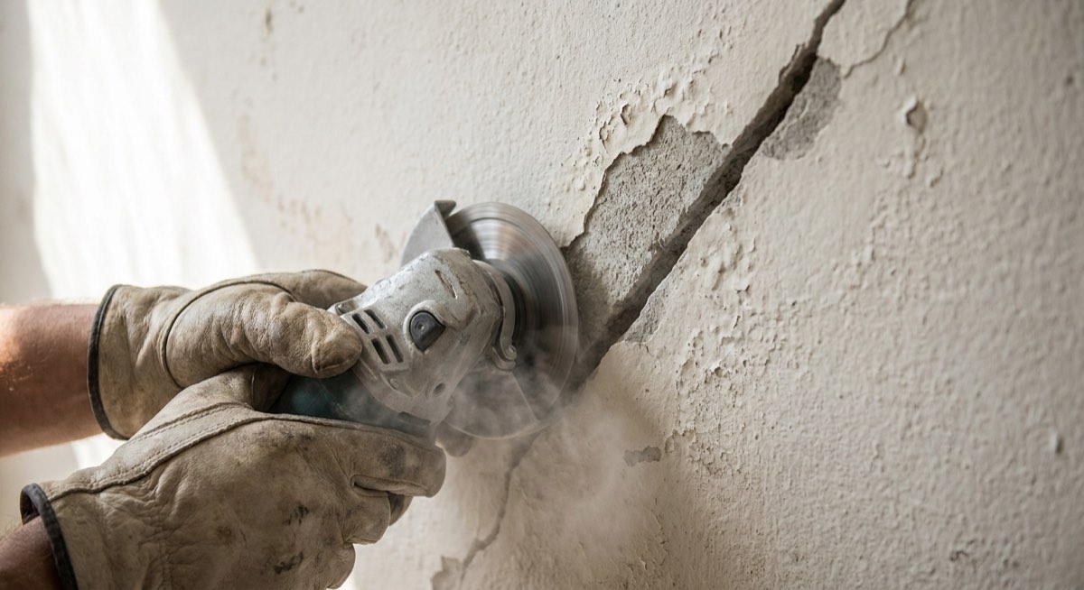
Break out and prepare the substrate
Saw-cut the perimeter about 10 mm deep to leave a square edge, then break back to sound concrete with light breakers rather than heavy ones that micro-crack the substrate. Continue 20-25 mm clear behind every exposed bar. Finish with grit blasting or high-pressure water.
Bond and place the reinstatement
Apply the specified bond coat and place the repair material wet-on-wet inside the overlay window for the grade supplied and the ambient temperature, which for a standard-grade epoxy bonding agent is about 90 minutes at 20 degrees C and about an hour at 30 degrees C. Build in lifts within the stated per-pass thickness, scratch-key each lift, and compact firmly behind and around the reinforcement rather than skimming over it.
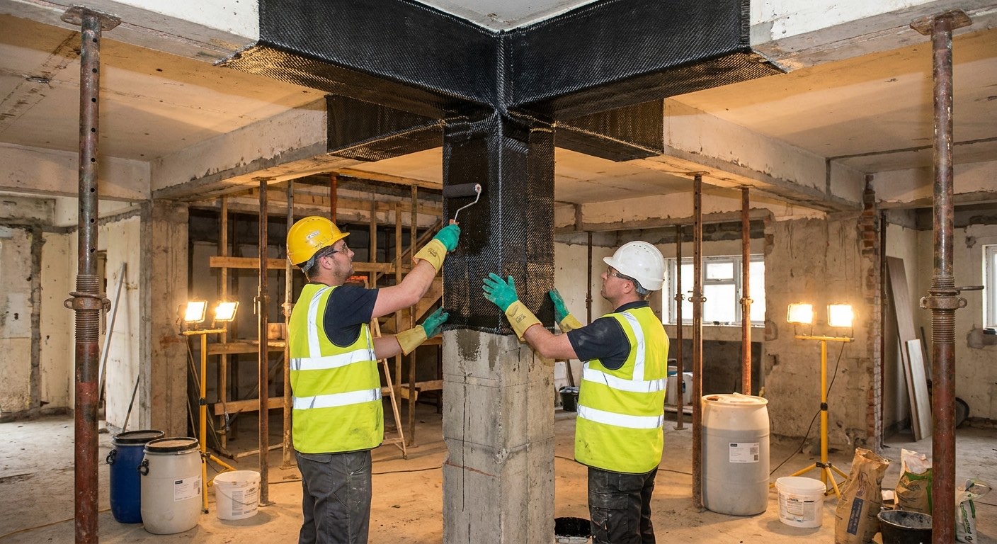
Externally bonded FRP strengthening
Carbon or glass fibre, either as a dry unidirectional fabric wet-laid in epoxy saturant or as a factory-pultruded plate bonded with a thixotropic epoxy. The cured composite carries tension the original section can no longer supply. Load upgrades, column confinement for seismic retrofit, and slabs where openings have been cut. Adds a few millimetres of thickness, needs no props once cured, and can be installed in occupied buildings over a weekend shutdown.
Systems compared, including where each one fails
Every system here is one Space Arc Engineering both supplies and applies, so the limitations listed are the ones we see on site rather than the ones in a brochure.
Polymer-modified cementitious repair mortar (hand-applied)
A factory-blended dry powder of Portland cement, graded silica aggregate and a redispersible polymer, gauged with water only. The polymer film raises bond and reduces permeability; the mortar is thixotropic enough to hold on vertical and overhead faces without formwork.
The default for patch repair of carbonation-driven spalling on columns, beams and soffits. Modulus and thermal movement sit close to the parent concrete, so the patch does not debond under terrace thermal cycling.
It cannot stop corrosion in chloride-contaminated concrete left around the patch. It also crazes and debonds if placed on substrate above roughly 40 degrees C or if curing is cut short, routine on NCR sites in May.
Typical spec. EN 1504-3 Class R4 requires a minimum 45 MPa compressive strength at 28 days and a minimum 2.0 MPa bond by pull-off; Class R3 is the 25 MPa / 1.5 MPa class. Typical Class R4 patch mortars deliver 45-60 MPa. Apply 5-50 mm per lift by trowel, high-build grades to 65 mm on vertical faces without formwork. Bond coat wet-on-wet, scratch-key each lift, wet cure 3 days minimum and 7 days in summer.
Poured micro-concrete and rapid-set patch concrete
Pre-bagged shrinkage-compensated micro-concrete with coarser graded aggregate, mixed to a flowing consistency and poured into formed bays. It self-compacts around congested reinforcement where a trowelled mortar would bridge and leave voids. Rapid-set grades reach traffic strength in hours.
Deep section loss and heavily congested zones: pavement bays, aprons, loading docks and ramps where sections exceed 50 mm and the asset must reopen the same shift.
Most pre-bagged grades in this class are horizontal-only. Vertical column and beam jacketing needs a flowable grade plus watertight shuttering, vents and a head of material; sites that improvise formwork get honeycombed jackets worse than the original defect.
Typical spec. 25-100 mm nominal, up to 250 mm when bulked with 10 mm aggregate. Pour in bays not exceeding about 4 m2 against a saturated surface dry substrate. Rapid grades reach roughly 20-30 MPa in 2-4 hours and 50-65 MPa at 28 days; open to wheeled traffic 2-4 hours at 25 degrees C.
Wet-process sprayed repair mortar
Repair mortar or concrete conveyed wet to a nozzle and projected onto the substrate at velocity, with a set-accelerating admixture dosed at the nozzle. Compaction comes from impact rather than trowel pressure, so build thickness per pass rises sharply and productivity transforms.
Large continuous soffits, tunnel linings, water-retaining walls and full-face repairs where hand application would take weeks. Production of several hundred square metres a day is realistic with a competent nozzleman.
Uneconomic below roughly 200 square metres because of plant mobilisation. Rebound waste, shadowing behind congested bars and nozzle distance discipline all depend on operator skill; a poor nozzleman produces voids you cannot see until you sound the surface.
Typical spec. Wet-spray a Class R4 mortar, minimum 45 MPa compressive at 28 days and 2.0 MPa bond, at 20-75 mm per pass on vertical faces and 20-50 mm overhead. Accelerating admixture metered at the nozzle from about 5 litres per 100 kg cementitious, confirmed by site trial panel. Sound the finished face for hollowness before curing wet for 7 days.
Epoxy resin crack injection
Two-part epoxy resin injected under pressure through surface-mounted ports into a crack sealed at the face. It cures rigid and typically stronger than the concrete, welding the two faces so the section transfers tension across the crack again.
Dormant structural cracks in beams, columns, rafts and water-retaining walls where load transfer must be restored. Works on damp substrates and gives a monolithic section with no visible thickness added to the member.
It is the wrong answer for a live crack. Anything still moving under thermal or live load will simply re-crack alongside the rigid resin line. Epoxy also refuses to travel into a crack that is actively running water.
Typical spec. Crack widths about 0.3-9 mm. Ports at 150-300 mm centres or roughly the member thickness, whichever is less. Seal the crack face with a thixotropic epoxy paste, inject at 2-4 bar from the lowest port upward until resin shows at the next, then cut ports and grind flush after 24-48 hours.
Water-reactive polyurethane injection
Low-viscosity polyurethane that reacts with water present in the crack and expands into a closed-cell, slightly flexible seal. The reaction is driven by the leak itself, so the wetter the crack the better the system performs.
Active leaks: basement rafts and walls, lift pits, water tanks, tunnel joints and terrace-slab cracks in the monsoon. It stops water fast and tolerates small ongoing movement without debonding.
It restores no structural capacity, so it must not be substituted for epoxy on a load-path crack. Over-injection can jack a crack open, and foam that cures against a dry face shrinks back and lets the leak return.
Typical spec. Packers drilled at 30-45 degrees to intersect the crack at mid-depth, 200-400 mm centres, staggered either side of the crack. Pre-flush with water where the crack is only damp. Inject at 60-150 bar with a single-component pump, then follow with a rigid resin where load transfer is also required.
Embedded galvanic and hybrid anodes
Discrete zinc units in an alkali-activated cementitious shell, tied to the reinforcement. The zinc corrodes preferentially and delivers a small protective current to the steel, holding it passive without any external power supply or ongoing monitoring.
The only practical way to stop incipient-anode corrosion at the edge of a patch in chloride-contaminated concrete. Essential on coastal structures, car park decks, sea-facing balconies and elements where chloride has diffused through sound-looking cover.
Current output falls in dry, well-ventilated interior concrete where resistivity is high, so a Delhi terrace parapet may get less protection than a Mumbai jetty. Anodes are also useless if the tie is not electrically continuous with the bar.
Typical spec. Perimeter units tied to cleaned steel at roughly 300-600 mm centres around every patch, with type and quantity set by chloride load and steel density. Drill-in units on a designed grid through sound but contaminated concrete at 20 mm minimum cover. Verify continuity before encasement.
Externally bonded FRP strengthening
Carbon or glass fibre, either as a dry unidirectional fabric wet-laid in epoxy saturant or as a factory-pultruded plate bonded with a thixotropic epoxy. The cured composite carries tension the original section can no longer supply.
Load upgrades, column confinement for seismic retrofit, and slabs where openings have been cut. Adds a few millimetres of thickness, needs no props once cured, and can be installed in occupied buildings over a weekend shutdown.
Capacity is governed by the bond and the substrate tensile strength, not by the fibre. It is passive: it only picks up load applied after it has cured, so unless the member is propped and unloaded during installation the existing dead-load stress stays in the original section. It performs poorly in fire without rated encasement, and is worthless over concrete that has not been repaired first.
Typical spec. Grind the substrate to remove laitance and pull-off test to ASTM C1583, target above 1.5 MPa with failure in the concrete. Primer 0.25-0.6 kg/m2, saturant 0.6-1.0 kg/m2 per fabric layer; plates 1.2-1.4 mm in a 1-2 mm glue line at about 2 litres/m2. Protect from UV, full cure 7 days.
Epoxy resin repair mortar
A three-component solvent-free epoxy binder with graded silica filler, trowelled like a mortar but with almost no permeability. It carries no Portland cement, so acids that dissolve a cementitious matrix have nothing to attack.
Sewage treatment works, effluent channels, sugar and distillery floors, battery rooms and any surface exposed to biogenic sulphuric acid or chemical spillage. Also the right choice for arris reinstatement and thin high-abrasion repairs.
Thermal expansion is two to three times that of concrete, so large areas exposed to sun or steam debond at the edges. The dense trowel grades are horizontal and vertical only; overhead work needs a lightweight high-build epoxy grade. It also needs a substrate free of standing water and costs several times a cementitious repair.
Typical spec. 5-50 mm horizontal in one pass and up to 12 mm per pass vertical, 5 mm minimum; overhead needs a high-build grade. Substrate blast-cleaned and free of standing or moving water. The dense grades will cure on damp concrete but must not be applied under running water. Prime horizontal substrates with an epoxy primer and apply while the primer is still tacky. Roughly 70 MPa at 7 days and water absorption near 0.2 percent. Do not place below 5 degrees C or where the temperature is 5 degrees C and falling.
Why this fails on Indian sites
Most failures are not product failures. These are the ones Space Arc Engineering’s applicators get called in to put right, usually years after the original job.
The incipient anode ring
- What you see
- A neat patch repair looks perfect for a year, then a fresh crack appears in a ring 100-300 mm outside the patch edge and new spalling follows within the next monsoon.
- Root cause
- The new alkaline, chloride-free mortar repassivates the steel inside the patch. The surrounding chloride-contaminated concrete becomes anodic by comparison, and corrosion current concentrates immediately outside the repair boundary.
- How to prevent it
- Install galvanic anodes tied to cleaned steel around every patch perimeter, or accept a wider break-out that removes the contaminated concrete. Chloride profiling before pricing tells you which of the two is cheaper on that structure.
Breaking out only what you can see
- What you see
- Repairs fail at the interface within two monsoons and the mortar comes away in sheets with rust staining on its back face.
- Root cause
- Break-out stopped at the visible spall and at the front of the bar. Corrosion product on the rear of the reinforcement was never removed, and the mortar never keyed behind the steel, so there is no mechanical lock.
- How to prevent it
- Break back 20-25 mm clear behind the bar all the way round and feather-edge nothing. Make the sounded area, not the visible area, the measured quantity in the BOQ so the contractor is not penalised for finding more.
Curing abandoned in the Indian summer
- What you see
- Fine random cracks across the new mortar within 48 hours, hollow patches at six months, and pull-off results well below the datasheet value.
- Root cause
- Substrate at 45-50 degrees C on a May afternoon in NCR pulls mix water out of the mortar before hydration completes. Hessian is laid once at the end of the shift and never re-wetted overnight.
- How to prevent it
- Restrict placement to early morning or night, bring the substrate to saturated surface dry and pre-cool it, and specify a named curing regime with a re-wetting frequency and a signed curing log rather than the word cure.
Epoxy injected into a crack that is still moving
- What you see
- A parallel crack appears 10-30 mm from the injected line within one thermal season, most often on a terrace beam or a long unjointed slab.
- Root cause
- The crack was thermal or live-load driven rather than a one-off overload. Cured epoxy is stiffer than the surrounding concrete, so the continuing movement simply finds the next weakest plane.
- How to prevent it
- Fit crack gauges and read them across at least one hot and one cool period before specifying resin. Live cracks need a flexible seal, a movement joint, or strengthening that removes the cause of the movement.
Bond coat overcoated outside its window
- What you see
- The repair sounds hollow when tapped and lifts cleanly off the substrate, leaving a glassy or chalky film on both faces.
- Root cause
- The epoxy bond coat was allowed to cure before the mortar went on, or an acrylic or SBR coat was left to dry and then re-wetted, which re-emulsifies the polymer film into a debonding layer.
- How to prevent it
- Place mortar wet-on-wet inside the stated overlay window, which for a standard-grade epoxy bonding agent is measured in tens of minutes rather than hours and shortens sharply as temperature rises. Re-coat the area if the window is missed, and verify a sample of completed repairs by pull-off test to ASTM C1583.
Repairing the soffit while the deck above still leaks
- What you see
- A car park or terrace soffit is repaired and repainted, and rust staining returns through the new finish within one or two monsoons.
- Root cause
- The repair addressed the consequence, not the mechanism. Water and dissolved chlorides continue to enter from the trafficked surface above and reach the same reinforcement from the other side.
- How to prevent it
- Sequence the deck waterproofing or traffic coating above before the soffit repair, or hold soffit finishes until the source is proven dry. Write that sequence into the programme, not only into the specification.
Comparison table
| System | Typical build or crack range | Strength (28 days unless noted) | Return to service | Best-fit condition |
|---|---|---|---|---|
| Polymer-modified repair mortar, hand-applied | 5-50 mm per lift; high-build to 65 mm vertical | 45-60 MPa compressive (R4 minimum 45 MPa); bond 2.0 MPa minimum | 3-7 days wet cure before coating | Carbonation spalling on columns, beams, soffits |
| Poured micro-concrete / rapid patch concrete | 25-100 mm, to 250 mm bulked; bays up to 4 m2 | 20-30 MPa at 2-4 hours; 50-65 MPa at 28 days | 2-4 hours to wheeled traffic | Deep horizontal loss: pavements, aprons, ramps |
| Wet-process sprayed repair | 20-75 mm per pass vertical; 20-50 mm overhead | 45-60 MPa compressive (R4 minimum 45 MPa) | 3-7 days wet cure | Large soffits, tunnels and tanks above 200 m2 |
| Epoxy resin crack injection | Cracks 0.3-9 mm; ports at 150-300 mm centres | Resin 60-95 MPa compressive | 24-48 hours to full load | Dormant structural cracks, dry or damp |
| Water-reactive polyurethane injection | Cracks from 0.1 mm; packers 200-400 mm centres | No structural capacity by design | Leak stops in minutes to hours | Actively leaking or slightly moving cracks |
| Embedded galvanic or hybrid anode | Discrete units, 300-600 mm centres, design-set | Not applicable; current output governs | Protective current from encasement | Chloride-contaminated concrete, patch perimeters |
| Externally bonded CFRP fabric or plate | Fabric 200-600 gsm; plate 1.2-1.4 mm thick | Fabric above 3,000 MPa; plate above 2,400 MPa tensile | 7 days to full cure | Flexural, shear and seismic confinement upgrades |
| Epoxy resin repair mortar | 5-50 mm horizontal; up to 12 mm per pass vertical | About 70 MPa at 7 days; water absorption near 0.2% | 24-48 hours to service | Sewage H2S, effluent, acids, high abrasion |
The standards this work is specified against
Quote these in your tender documents. They are what a third-party inspector will check against, and Space Arc Engineering can supply the batch and compliance paperwork to match.
Sets the exposure classification, nominal cover, minimum cement content and maximum water-cement ratio. A repair has to reinstate the cover and durability the code requires, not merely fill the hole.
The framework standard. It defines assessment, cause determination and the numbered protection and repair principles, which is the language a defensible repair specification should be written in.
Classifies repair mortars and concretes as R1 to R4 on compressive strength, bond, elastic modulus and restrained shrinkage. R4 requires at least 45 MPa compressive strength and 2.0 MPa bond, against 25 MPa and 1.5 MPa for R3, and is the normal requirement for structural reinstatement.
The half-cell potential mapping method used to locate active corrosion before break-out. Note the current title says Corrosion Potentials; older specifications citing Half-Cell Potentials are referring to a superseded edition of the same active standard.
The pull-off test that proves surface preparation before FRP or overlay work and verifies repair bond afterwards. Specify both a minimum value and the required failure mode.
Current Indian method for ultrasonic pulse velocity assessment, superseding the UPV provisions of IS 13311 Part 1. Useful for grading concrete quality and detecting internal voids before repair.
Products we recommend and stock
Every product below is one Space Arc Engineering stocks as an authorised distributor. Fosroc is strongest here on the electrochemical side. The Galvashield anode range covers patch-perimeter, drill-in and hybrid units under one design methodology, which means corrosion control, repair mortar and strengthening can be documented as a single compatible system rather than assembled from three suppliers. The Renderoc and Patchroc mortars are competent Class R4 systems rather than uniquely superior ones; where Fosroc genuinely earns the specification is when all three layers of the repair have to be evidenced together.
Distributor and applicator, not just a supplier
Repair specification and repair execution fail in different ways, and most disputes on a rehabilitation job sit exactly at that seam. Space Arc supplies the Fosroc range under current authorised distribution, sources other principals’ systems where the diagnosis calls for them, and also puts crews on the structure, so break-out depth, anode continuity, bond-coat windows and curing logs are our accountability rather than a supply note. It also means we will tell you before dispatch when the material you asked for is wrong for the diagnosis, instead of after the patch fails.
- Authorised distributor for Fosroc, Sika, Dr. Fixit, MC-Bauchemie, UltraTech, Master Builders Solutions, STP and D-Seal
- In-house application crews across Delhi NCR, with pan-India project supply
- Specification support before you tender, and site supervision during execution
- Genuine, batch-traceable material direct from authorised channels
Concrete repair – frequently asked questions
What is the correct sequence for concrete spalling repair?
Why does concrete repair fail after two years?
Should I use epoxy or polyurethane injection for a leaking crack?
How deep should you break out around corroded rebar?
Is micro concrete or repair mortar better for column jacketing?
What compressive strength and bond does EN 1504-3 Class R4 actually require?
Do I still need anodes if I use a zinc-rich primer on the rebar?
Can concrete repair be done during the monsoon in Delhi NCR?
How do you repair concrete in a sewage treatment plant?
Related guides
How to Repair Spalled & Damaged Concrete
A practical, cross-brand guide to diagnosing and repairing spalled, delaminated and damaged concrete — from rebar…
How to Fix Wall Cracks: Causes & Solutions
A practical, cross-brand guide to diagnosing wall cracks and repairing them correctly: structural vs non-structural,…
Structural Strengthening with CFRP: A Practical Guide
A practical, cross-brand guide to strengthening concrete and masonry with carbon fibre (CFRP) wraps, laminates and…
Not sure which specification your project needs?
Send us the substrate, the exposure and the area. Space Arc Engineering will come back with a specification, a bill of quantities and the datasheets to support it.